
ENJOY
http://WWW.RAFSA.CO.ZA
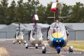
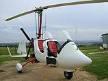
SOME MORE RAF 2000 GTX SE FI FOTOS
Moderators: Gyronaut, Condor, FO Gyro
SOME MORE RAF 2000 GTX SE FI FOTOS
- Attachments
-
- RAF 2000 GTX SE FI 2.5 (FRANKIE).jpg (96.63 KiB) Viewed 4112 times
-
- RAF 2000 GTX SE FI 2.5.jpg (94.14 KiB) Viewed 4113 times
Good instructors always speak well about all flying machines.
Bad instructors speak badly about machines they cannot fly.
Bad instructors speak badly about machines they cannot fly.
-
old no 7
- Nothing beats flying

- Posts: 442
- Joined: Mon Jan 07, 2008 8:32 pm
- Location: Looking up at the sky
Re: SOME MORE RAF 2000 GTX SE FI FOTOS
Am I being dof but aren't horizontal stabilisers standard issue on RAF yet?
What about PIO?
What about PIO?
ZU-f-ALL
Re: SOME MORE RAF 2000 GTX SE FI FOTOS
What is the Horizontal "Wing" just above the engine. Surely that will do the same work?
Auto-Gyro Calidus ZU-RRG
Re: SOME MORE RAF 2000 GTX SE FI FOTOS
Hi Old no 7
Here is some info for all that has the Q why does the RAF have no HS.
PIO - Pilot induced ossolation - PIO is not caused by the aircraft but by the pilot, other wise they have to call it Aircraft induced Ossolation.....
Design Innovations Of The RAF 2000 Gyroplane
Rotary Air Force Marketing Inc. (RAF) has dedicated countless hours of research and development to ensure that our clients receive a very controllable, user-friendly aircraft. The following is a brief history about the evolution of the RAF 2000 Gyroplane from an open frame aircraft to the fully enclosed, side-by-side, two-place aircraft that you see today on the flight lines and in the air. You will also find that there are some comparisons between the RAF 2000 Gyroplane and other gyroplanes that are currently available.
Two-Part Mast System
Many of the gyroplane designers copied the early basic design of the 2x2" mast. Or opted for a rigid mast configuration. The mast had the engine mounted at some point between gimble head and keel. The thrust line became a pivot like a teeter-totter. Provided that the dynamic weight of the rotor was equal to the weight of the pilot and fuel, then the aircraft flew quit nicely. However, the rotors are always changing in lift and drag. As the drag increased, the mast would bend back. As the air equalized in the rotor disc, the drag reduced. This allowed the mast to spring back to its normal spot. This caused all kinds of control issues for the new pilots.
RAF discarded this 2x2" tube, and replaced it with the more robust and rigid 2x4" mast. The 2x4" mast, (now the engine pylon) is about 48" long, and extends about 6" over the pilot's head. The upper part of this 2x4" tube is stuffed with a dressed piece of hardwood. Two holes are drilled through the tube and wood, spaced about 8" apart. A rubber bushing is inserted through the top hole and a center of gravity adjuster in the bottom hole. Two cheek plates (2x4" x 3/16" x 36") are attached to the sides of the mast with two -AN 36 bolts extending through one plate, the rubber bushing in the mast, and out through the other plate. The second bolt goes through one plate into the patented C of G adjuster and out through the second plate. The gimble head is then attached to these cheek plates. The rotor mast (cheek plates) could now flex back and forth and side-to-side independently as the rotor blades moved in flight.
Push Tube Configuration
Unlike the "other" gyroplanes on the market today, the push tubes on the RAF gyroplane are out in front of the gimble head at an opposing angle to the mast. Why put the push tubes at an opposing angle to the mast? This is done to stop resonant vibration in the control push tubes. The push tubes are put into tension when the pilot makes a control input to descend, thus the push tubes cannot bend slightly and resonant vibrations do not like to travel down an opposing angle. When the RAF pilot makes a control input to descend or to correct a slight pitch up, only one thing happens, the gyroplane descends in a controllable attitude. The push tubes do not spring straight - the thrust line does not change. It is a controllable descent, even in a high-speed environment.
On the RAF gyroplane, the push tubes are at an opposing angle (out the front of the head), thus when a wind gust or unstable air hits the rotor disc the cheek plates flex back slightly causing the push tubes to hold down on the front of the torque tube this prevents large changes in the rotor blades angle of attach to the forward motion. The same holds true for a descent. This action reduces the movement of the rotor lift vector with relation to the C of G of the aircraft.
The RAF 2000 Gyroplane push tubes are also SPLIT at midpoint. This split push tube control system was incorporated so that any vibration would stop at midpoint and not affect the lower control yoke going into the joystick. The split push tube design also allows the owner to be able to fold down the mast for transportation or storage.
Good instructors always speak well about all flying machines.
Bad instructors speak badly about machines they cannot fly.
Bad instructors speak badly about machines they cannot fly.
Re: SOME MORE RAF 2000 GTX SE FI FOTOS
The RAF 2000 Rotor Stabilator (Patent Pending)
Gyroplanes are a unique aircraft clearly distinguishable from airplanes. The most obvious
contrast is the rotating primary lift surface of the gyroplane compared to the fixed wing of the
airplane. The primary lifting
surface of the gyroplane also acts
as a control surface for pitch and
roll movements whereas a fixedwing
uses much smaller ailerons
and elevators. Furthermore, this
lifting surface suspends the
fuselage against gravity during
flight. Rotational freedom about
two axes exists at the joint between
lifting surface and fuselage. The
pilot manipulates these two free
rotational axes for rotor control
from the fuselage.
These design differences translate to controllability differences. In comparison to fixed-winged
aircraft, rotor rotation and size provides improved controllability at low airspeeds. In fact current
gyroplanes display greater agility than airplanes throughout the airspeed range. Advantaged by
the rotary-wing, gyroplane control responsiveness variates less versus airspeed than with fixedwing
airplanes. However, control
inputs still gain sensitivity as
forward airspeed increases. Some
pilots find piloting tiresome if
turbulent air jostles the rotor disc at
higher flight speeds. Novice and
non-proficient pilots may be prone
to over-control in these same
conditions. The two free rotational
axes between fuselage and rotor disc
removes the ingrained visual
reference between wing and horizon
for fixed-wing conversion pilots.
Rotor motion independent from
fuselage motion creates control
system movements that further
complicate conversion from the
fixed-stick fixed-wing practice.
Good instructors always speak well about all flying machines.
Bad instructors speak badly about machines they cannot fly.
Bad instructors speak badly about machines they cannot fly.
Re: SOME MORE RAF 2000 GTX SE FI FOTOS
INfo cont in new tread "RAF info CONT"
Good instructors always speak well about all flying machines.
Bad instructors speak badly about machines they cannot fly.
Bad instructors speak badly about machines they cannot fly.

Re: SOME MORE RAF 2000 GTX SE FI FOTOS
Nice photo Eben.
I see in the Sa flyer you have regitered 18 RAF's in one month.
Well done
I see in the Sa flyer you have regitered 18 RAF's in one month.
Well done
Re: SOME MORE RAF 2000 GTX SE FI FOTOS
Hi T
Thanks yes we did register 18.
Regards
SARAF
Thanks yes we did register 18.
Regards
SARAF
Good instructors always speak well about all flying machines.
Bad instructors speak badly about machines they cannot fly.
Bad instructors speak badly about machines they cannot fly.
Who is online
Users browsing this forum: No registered users and 2 guests