I am very interested in the best cooling on VW motors.
Micro Cooling
-
Bennie Vorster

- Toooooo Thousand

- Posts: 2111
- Joined: Sun Nov 13, 2005 1:57 pm
- Location: Newcastle
- Contact:
Micro Cooling
Is there anyone that is willing to post picks of the cooling instelations pleazzzzzzzzzzzzzz.
I am very interested in the best cooling on VW motors.
I am very interested in the best cooling on VW motors.
Growing old is far more dangerous than flying !!!
Bennie Vorster
083 277 5110
Bennie Vorster
083 277 5110
-
Bennie Vorster
- Toooooo Thousand
- Posts: 2111
- Joined: Sun Nov 13, 2005 1:57 pm
- Location: Newcastle
- Contact:
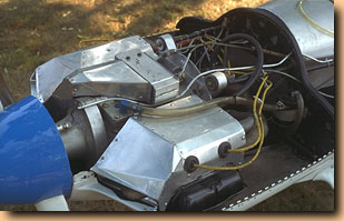
While we are on the subject of cooling, please look at this otherwise pretty sanitary VW installation. The problem I have with it is the lack of cooling air into the fins that surround the exhaust ports. See the area between the forward plug, and the forward exhaust valve? That's the most critical area for cooling, and in this installation, it gets NO AIR. That's not right. Even if your CHT's look fine, you're cooking your exhaust valves, and the temperature differential between various parts of the heads will promote cracking. Although I like and respect Richard, his plane, and his workmanship, his cooling setup as he implemented it makes this mistake; it doesn’t shove any air into the fins around the exhaust valves. Since his cylinders are out in the breeze, maybe he’ll get away with it. Same bad practice here. I wish I had a picture of prop maker Ed Sterba's Sonerai engine: his installation had it all done right, with little auxiliary plenums directing air UP (as I recall) through those exhaust port fins. Blueberry’s engine does it right, Serge Vidal does it right, Jim Hardy’s engine does it right. Look at the way the stock TOP tin is arranged.
The baffling patterns Great Plains sells are essential for any installation, even if the engine is out in the breeze, you can use the bottom of the patterns to save a lot of time building your "Elephant Ears". The


Get Cool!
Factors to consider when improving engine cooling
By Richard Mole
In this second article, I will describe a systematic approach to improving engine cooling based on personal experience with a Limbach L2000 powered Jodel D18.
Why do temperatures vary from day to day?
Many VW conversions, and some other small engines, use carburettors such as the Zenith-Stromberg carburettor, which lack cockpit control over the mixture. These carburettors also lack temperature compensation. A change in atmospheric conditions can thus have a major effect on the air fuel ratio, and thus engine temperatures. The density altitude on the runway I use at an airfield in the Midlands, for example, varied from minus 1,500 feet to plus 2,500 feet over the course of last year. My engine ran much leaner on the ground at minus 1,500 feet on the International Standard Atmosphere, on a cold, crisp, high pressure day in Winter, to the point where pre-detonation became a distinct possibility. Conversely, it would run much richer and cooler on a humid Summer's day, in the middle of a depression.
It may be worth investing in a small portable meter, sold in car accessory retailers, for measuring the exhaust CO%. This could be used to monitor mixture strength scientifically and allow you to properly adjust the mixture on the ground, so avoiding the danger of pre-detonation. Unlike the car driver, it is most unlikely that a pilot will be able to hear 'pinking', which is the harbinger of burnt valves and valve seats. I now have the latest specification carburettor for my Limbach engine. This has a different jet and needle which seems to provide a better mixture at partial throttle settings in the cruise, and it also seems much less prone to effects brought on by seasonal changes.
The Exhaust Gas Temperature (EGT) is closely correlated to mixture strength and the EGT instrument is essential for monitoring engine health. The Cylinder Head Temperature gauge is also a vital instrument since it is essential to know the CHT of each cylinder head when undertaking development work. If the hottest CHT gets too hot, throttle back!
Of course, variations in cruise altitude can make a considerable difference to engine temperatures for other reasons. Once again, the air pressure at the cruising altitude and the outside air temperature jointly determine the Relative Air Density. The relative air density will determine the mass flow rate of the cooling air, at a given true air speed. Now the heat convected away by the cooling air depends on both its temperature rise and its mass flow. So the engine temperatures are a complicated consequence of variations in both the air:fuel mixture and the cooling medium.
Many other factors can contribute to varying the oil and cylinder temperatures. For example, if you change the propeller from a 'cruise' to a 'climb' propeller then you may find higher CHTs in the climb, at the same climbing ASI, because the engine will be turning faster and developing more power. On the other hand, cruise CHTs at the same rpm may be lower because the power output (and thus the ASI) will be reduced - a manifold pressure gauge provides a useful, if approximate, indication of power output.
What are acceptable temperatures?
In almost every strut you will hear stories of hot engines, particularly VW conversions, giving rise to a host of problems such as unreliability or restricted operational performance. There is about a 20C difference between the temperature in the cruise, at which cylinder heads and valves are good for, say, a thousand hours rather than a hundred hours. So what are acceptable temperatures for a VW based aero engine? There are no hard and fast rules, but the following table gives my best assessment, for what its worth (it does not apply to other engine types).
Judgement CHT Climb CHT cruise Oil cruise
Excellent Under 190C (374F) 155 - 159C (311 - 318F) 80C (175F)
Very good 191 - 200C (376 - 392F) 160 - 164C (320 - 327F) 78 - 82C (172 - 180F)
Pretty good 201 - 210C (394 - 410F) 165 - 169C (329 - 336F) 75 - 85C (167 - 185F)
Acceptable 211 - 220C (412 - 428F) 170 - 174C (338 - 345F) 70 - 90C (158 - 194F)
Rather high 221 - 230C (430 - 446F) 175 - 180C (347 - 356F) 91 - 95C (196 - 203F)
Too high over 230C (446F) over 180C (356F) over 95C (203F)
Do not take CHT and EGT instrument readings at face value
Most budget-priced instruments, such as the Westach range, are calibrated to give accurate readings when the 'cold junction' of the thermocouple is at a particular temperature, such as 76F. If the cold junction is actually at 66F, say on a spring day, then the instrument will over-read by 10F. But on a really hot summer day, when the cold junction is at 86F, it will under-read by 10F.
The cold junctions in my D18 are just behind the instrument panel. I can reduce by 20C the gauge readings of the CHTs and EGTs on a cold winter's day just by operating the cabin heat control, which sends a nice stream of warm air over the cold junctions. So any comparison of EGTs and CHTs from simple uncompensated thermocouple instruments cannot be based just on the gauge readings.
This is no academic matter. The actual temperatures, and not the instrument readings, will largely determine the life of your valves and valve seats. You need a thermometer to measure the cold junction temperature in order to apply a suitable error correction! Fortunately you can buy a cheap digital thermometer with a remote sensor from car accessory retailers; just tape the sensor to the cold junctions. This will allow you to calculate the gauge error - the difference from 66F (24C). Ensure that all temperatures are stable before recording them and don't use the cabin heater!
The cooling air is warmed as it convects away the waste heat. So the performance of the cooling system is assessed on the basis of the increase in the (corrected) CHT over and above the ambient air temperature. This means you must also record the Outside Air Temperature (OAT).
Criteria for engine cooling
correct the EGT and CHT instrument readings to find how hot your engine really is (i.e. whether your valves can take it)
use the amount by which the corrected CHT exceeds the Outside Air Temperature to decide whether your latest modification to the cooling system is delivering the goods
Make careful instrument readings (avoiding parallax error) and systematic records. A spreadsheet tool helps to organise records, make the corrections described above, and it readily calculates average values. Unless you proceed with care, it is perfectly possible to make a change in the cooling system, such as a revision in the baffle arrangements, and be totally misled by the values shown on the EGT and CHT instruments. For example, even though the corrected CHTs might have increased, the modification may still have delivered lower temperatures than you would have experienced without the modification - simply because the most recent test flight was done on a much hotter day!
Assessing the effectiveness of a change in the cooling arrangements is really quite complicated. The EGT and CHT can be affected both by QNH and by temperature; relative density is only part of the story (many GPS handhelds are programmed to estimate density altitude from temperature and pressure). Therefore, you should first try to compile sufficiently complete records to be able to say how engine temperatures vary with density altitude and Outside Air Temperature. Nobody should pretend that this sort of exercise is easy, nor is it likely to be very precise. On the other hand, you just cannot afford to ignore these effects if you are serious about improving the cooling arrangements.
Even then, you must also realise that the instrument readings will be 'noisy' as they are hardly precision instruments, of the sort that you would find in a professional development programme for a commercial aircraft. You will therefore need to work with average temperatures and trends. Don't be misled by changes that appear favourable and that you WANT to be real - they may just be within the normal range of variation.
Worked examples
Take the following data on cruise temperatures for example. The first row shows the actual instrument readings for the hottest cylinder. The second row gives the corrected temperatures, having removed the thermocouple error in the CHT and EGT readings. In this case the thermocouples were calibrated for cold junctions at 24C, and these junctions are under the instrument panel, which is at the Internal Air Temperature (IAT).
Note that the oil temperature gauge is a properly compensated instrument. An instrument that requires connection to the positive and negative buses and a sender input is LIKELY to be properly compensated - but check.
The CHT is about 172C (342F) and the EGT is 692C (1436F), which is acceptable in my book. The third row of the table gives the temperatures over and above the Outside Air Temperature (OAT). These are 67C for the oil and 159C for the CHT.
FLIGHT TRIAL #1 OAT deg C IAT deg C OIL deg C EGT deg C CHT deg C
Instrument Readings 13 16 80 700 180
Corrected readings
80 692 172
Temperatures over & above OAT
67
159
The same aeroplane is flown the next day at the same cruise rpm but there has been a marked improvement in the weather. The OAT has increased by 10C from 13C to 23C. Thus the actual Oil and CHT temperatures will be about 10C higher than before, all else being equal.
The hot and sunny day has raised the temperature under the bubble canopy to 30C which means that the EGT and CHT uncompensated instruments will under-read by 30-24 = 6C. Pre-flight checks sensibly included a large plastic bottle of chilled water for the pilot! The next table shows the new situation
FLIGHT TRIAL #2 OAT deg C IAT deg C OIL deg C EGT deg C CHT deg C
Instrument Readings 23 30 90 681 174
Corrected readings
90 687 180
Temperatures over & above OAT
67
157
Here, the oil temperature is still within limits; the instrument is a fully compensated unit. But the corrected CHT of 180C (360F) is barely acceptable even though the uncompensated CHT instrument shows only 174C (345F).
The following table summarises CHT considerations. It demonstrates the danger of being seriously misled by taking CHT gauge readings at face value and failing to take Outside Air Temperature into account. Only the final column has any real significance for cooling performance.
Flight Trial Uncorrected CHT Corrected CHT Uncorrected CHT
rise over OAT Corrected CHT
rise over OAT
#1 180C 172C 167C 159C
#2 174C 180C 151C 157C
Conclusion #2 is better by 6C #1 is better by 8C #2 is better by 16C #2 is better by 2C
But is the 2C reduction in the final column a REAL improvement? It is well within the range of experimental error and most probably due to the fact that the EGT has actually dropped by 5C, from 692C in the first trial to 687C on the second (NB the EGT has certainly has not reduced as much as the 19C that the instrument would have us believe i.e. from 700C to 681C). It can be very hard to disentangle the effects of measures to improve the cooling from changes that would have happened anyway! Particularly as you must be alert to the effect of other factors - my CHTs, for example, are very sensitive to drifting valve clearances. This example shows how hard it is to interpret cooling data even when it is carefully collected.
Making changes in the field
The following cooling development was followed with a Limbach L2000 in my Jodel D18. It is not really possible to say, with any real confidence, that a particular change resulted in a particular temperature drop. This is mainly because the impacts of changes are inter-related. For example, shell baffles are very effective in reducing CHTs if, but only if, there is a high enough pressure differential between the high and low pressure plenums.
1. The air intake geometry
Modifications were not too difficult because the cowl was glass fibre. I moved the intakes outboard for example, and thickened and faired the intake lip. The intakes were squared and moved forward very slightly. I tried to improve the ducting arrangements behind the inlets but found it impracticable to install a genuine diffuser as such. However, the top of the inlets were carefully faired into the cowl roof, and the bottom of the inlets were extended as far aft as possible. I also tested the effects of installing a full spinner rather than a skull cap spinner, or none at all.
2. The high pressure plenum
I changed the side baffles to increase the plenum volume and spent a long time improving the sealing arrangements. Shiny aluminium tape was used on the under surface of the cowl to reflect radiant heat and leave a tell tale to verify that baffles were sealing properly. A removable mask was introduced to partially shield the oil cooler in winter to maintain appropriate oil temperatures.
3. The shell baffles
There are various ways of holding the shell baffles in contact with the fins of the cylinders and cylinder heads. I used long stainless steel hose clamps and ties around the two adjacent cylinders, so clamping the shell baffle at the front of the forward cylinder to the rear baffle around the aft cylinder. The CHTs reduced, as expected, when I exchanged my set of home made shell baffles, consisting of many interlocking components, for a Limbach set stamped out of a single sheet of aluminium on a rubber press. But I was quite surprised to find that the oil temperature actually increased! The old baffles had obviously leaked copiously and had been ventilating the sump. By improving the effectiveness of the oil cooler I was able to reduce the oil temperature which provided a further small decrease in CHTs.
4. The low pressure plenum
I found scope for straightening the flow and relocating obstacles such as Bowden cables away from the main flow. The arrangements for dumping surplus cabin heat were improved and better seals were introduced to seal the carburettor cold air supply. Cut-outs for the exhaust pipes were re-located further aft, near the firewall, and exhaust fairings were fitted. Early and ill-informed attempts to improve the cooling by making openings in the bottom cowl proved counter productive and they were blocked off.
5. The exit conditions
The cross sectional area, normal to the flow, was increased to about 50% over and above the intake area. Skirts were found to be draggy and sometimes affected the cooling adversely. Instead, a lipped aluminium doubler was used to stiffen the rear edge of the cowl so that it maintained its geometry under flight loads.
A final word of caution
It is important to ensure that your engine is maintained in top condition. Don't forget, if you use a Zenith-Stromberg type of carburettor, to be absolutely certain that the dash pot oil level is correctly maintained and that the diaphragm is fully serviceable. The plug gaps should be correct and the valves clearances must be meticulously maintained. Also be sure to check that the timing has not drifted. And you must keep a constant look out that the baffles are consistently well sealed; it is quite likely that a new fibre glass cowl, although a tight fit initially, will become a sloppy fit over time - it doesn't stretch but the high points are likely to be rubbed off. Even when all these factors are accounted for, you will still find some residual variation in CHTs and EGTs from day to day.
All this makes it quite hard to detect whether any modification to the cooling system has been beneficial rather than adverse. You may need to make small changes and acquire sufficient operational experience to be quite sure. But the longer you take, the greater the chance that the normal seasonal variation in atmospheric conditions will make problematic the interpretation of your data. It is therefore best to test fly intensively once a change has been made - bearing in mind that a warm engine may reach different temperatures in the climb than on the first flight of the day!
The picture is further complicated by the fact that you will probably want to use four CHT thermocouples. This is because a modification to the cooling system will affect the four CHTs to a varying extent. So in addition to the primary objective of reducing the highest CHT there is a secondary objective of reducing the temperature range - between the rear cylinders and the front cylinders for example - whatever the ambient conditions the engine must run within the greens at all times.
Of course, it goes without saying that nothing must be done to Permit aircraft without first consulting your PFA Inspector. Indeed some changes, such as installing a spinner, will first require PFA Engineering to issue an Engineering concession. The modifications to my engine installation required considerable effort over a protracted period. But now I have a contented engine that I sincerely hope will be reliable, and long lived. My thanks to my PFA Inspector, Martin Jones, for his enthusiasm and understanding during this testing time

The baffling patterns Great Plains sells are essential for any installation, even if the engine is out in the breeze, you can use the bottom of the patterns to save a lot of time building your "Elephant Ears". The
Get Cool!
Factors to consider when improving engine cooling
By Richard Mole
In this second article, I will describe a systematic approach to improving engine cooling based on personal experience with a Limbach L2000 powered Jodel D18.
Why do temperatures vary from day to day?
Many VW conversions, and some other small engines, use carburettors such as the Zenith-Stromberg carburettor, which lack cockpit control over the mixture. These carburettors also lack temperature compensation. A change in atmospheric conditions can thus have a major effect on the air fuel ratio, and thus engine temperatures. The density altitude on the runway I use at an airfield in the Midlands, for example, varied from minus 1,500 feet to plus 2,500 feet over the course of last year. My engine ran much leaner on the ground at minus 1,500 feet on the International Standard Atmosphere, on a cold, crisp, high pressure day in Winter, to the point where pre-detonation became a distinct possibility. Conversely, it would run much richer and cooler on a humid Summer's day, in the middle of a depression.
It may be worth investing in a small portable meter, sold in car accessory retailers, for measuring the exhaust CO%. This could be used to monitor mixture strength scientifically and allow you to properly adjust the mixture on the ground, so avoiding the danger of pre-detonation. Unlike the car driver, it is most unlikely that a pilot will be able to hear 'pinking', which is the harbinger of burnt valves and valve seats. I now have the latest specification carburettor for my Limbach engine. This has a different jet and needle which seems to provide a better mixture at partial throttle settings in the cruise, and it also seems much less prone to effects brought on by seasonal changes.
The Exhaust Gas Temperature (EGT) is closely correlated to mixture strength and the EGT instrument is essential for monitoring engine health. The Cylinder Head Temperature gauge is also a vital instrument since it is essential to know the CHT of each cylinder head when undertaking development work. If the hottest CHT gets too hot, throttle back!
Of course, variations in cruise altitude can make a considerable difference to engine temperatures for other reasons. Once again, the air pressure at the cruising altitude and the outside air temperature jointly determine the Relative Air Density. The relative air density will determine the mass flow rate of the cooling air, at a given true air speed. Now the heat convected away by the cooling air depends on both its temperature rise and its mass flow. So the engine temperatures are a complicated consequence of variations in both the air:fuel mixture and the cooling medium.
Many other factors can contribute to varying the oil and cylinder temperatures. For example, if you change the propeller from a 'cruise' to a 'climb' propeller then you may find higher CHTs in the climb, at the same climbing ASI, because the engine will be turning faster and developing more power. On the other hand, cruise CHTs at the same rpm may be lower because the power output (and thus the ASI) will be reduced - a manifold pressure gauge provides a useful, if approximate, indication of power output.
What are acceptable temperatures?
In almost every strut you will hear stories of hot engines, particularly VW conversions, giving rise to a host of problems such as unreliability or restricted operational performance. There is about a 20C difference between the temperature in the cruise, at which cylinder heads and valves are good for, say, a thousand hours rather than a hundred hours. So what are acceptable temperatures for a VW based aero engine? There are no hard and fast rules, but the following table gives my best assessment, for what its worth (it does not apply to other engine types).
Judgement CHT Climb CHT cruise Oil cruise
Excellent Under 190C (374F) 155 - 159C (311 - 318F) 80C (175F)
Very good 191 - 200C (376 - 392F) 160 - 164C (320 - 327F) 78 - 82C (172 - 180F)
Pretty good 201 - 210C (394 - 410F) 165 - 169C (329 - 336F) 75 - 85C (167 - 185F)
Acceptable 211 - 220C (412 - 428F) 170 - 174C (338 - 345F) 70 - 90C (158 - 194F)
Rather high 221 - 230C (430 - 446F) 175 - 180C (347 - 356F) 91 - 95C (196 - 203F)
Too high over 230C (446F) over 180C (356F) over 95C (203F)
Do not take CHT and EGT instrument readings at face value
Most budget-priced instruments, such as the Westach range, are calibrated to give accurate readings when the 'cold junction' of the thermocouple is at a particular temperature, such as 76F. If the cold junction is actually at 66F, say on a spring day, then the instrument will over-read by 10F. But on a really hot summer day, when the cold junction is at 86F, it will under-read by 10F.
The cold junctions in my D18 are just behind the instrument panel. I can reduce by 20C the gauge readings of the CHTs and EGTs on a cold winter's day just by operating the cabin heat control, which sends a nice stream of warm air over the cold junctions. So any comparison of EGTs and CHTs from simple uncompensated thermocouple instruments cannot be based just on the gauge readings.
This is no academic matter. The actual temperatures, and not the instrument readings, will largely determine the life of your valves and valve seats. You need a thermometer to measure the cold junction temperature in order to apply a suitable error correction! Fortunately you can buy a cheap digital thermometer with a remote sensor from car accessory retailers; just tape the sensor to the cold junctions. This will allow you to calculate the gauge error - the difference from 66F (24C). Ensure that all temperatures are stable before recording them and don't use the cabin heater!
The cooling air is warmed as it convects away the waste heat. So the performance of the cooling system is assessed on the basis of the increase in the (corrected) CHT over and above the ambient air temperature. This means you must also record the Outside Air Temperature (OAT).
Criteria for engine cooling
correct the EGT and CHT instrument readings to find how hot your engine really is (i.e. whether your valves can take it)
use the amount by which the corrected CHT exceeds the Outside Air Temperature to decide whether your latest modification to the cooling system is delivering the goods
Make careful instrument readings (avoiding parallax error) and systematic records. A spreadsheet tool helps to organise records, make the corrections described above, and it readily calculates average values. Unless you proceed with care, it is perfectly possible to make a change in the cooling system, such as a revision in the baffle arrangements, and be totally misled by the values shown on the EGT and CHT instruments. For example, even though the corrected CHTs might have increased, the modification may still have delivered lower temperatures than you would have experienced without the modification - simply because the most recent test flight was done on a much hotter day!
Assessing the effectiveness of a change in the cooling arrangements is really quite complicated. The EGT and CHT can be affected both by QNH and by temperature; relative density is only part of the story (many GPS handhelds are programmed to estimate density altitude from temperature and pressure). Therefore, you should first try to compile sufficiently complete records to be able to say how engine temperatures vary with density altitude and Outside Air Temperature. Nobody should pretend that this sort of exercise is easy, nor is it likely to be very precise. On the other hand, you just cannot afford to ignore these effects if you are serious about improving the cooling arrangements.
Even then, you must also realise that the instrument readings will be 'noisy' as they are hardly precision instruments, of the sort that you would find in a professional development programme for a commercial aircraft. You will therefore need to work with average temperatures and trends. Don't be misled by changes that appear favourable and that you WANT to be real - they may just be within the normal range of variation.
Worked examples
Take the following data on cruise temperatures for example. The first row shows the actual instrument readings for the hottest cylinder. The second row gives the corrected temperatures, having removed the thermocouple error in the CHT and EGT readings. In this case the thermocouples were calibrated for cold junctions at 24C, and these junctions are under the instrument panel, which is at the Internal Air Temperature (IAT).
Note that the oil temperature gauge is a properly compensated instrument. An instrument that requires connection to the positive and negative buses and a sender input is LIKELY to be properly compensated - but check.
The CHT is about 172C (342F) and the EGT is 692C (1436F), which is acceptable in my book. The third row of the table gives the temperatures over and above the Outside Air Temperature (OAT). These are 67C for the oil and 159C for the CHT.
FLIGHT TRIAL #1 OAT deg C IAT deg C OIL deg C EGT deg C CHT deg C
Instrument Readings 13 16 80 700 180
Corrected readings
80 692 172
Temperatures over & above OAT
67
159
The same aeroplane is flown the next day at the same cruise rpm but there has been a marked improvement in the weather. The OAT has increased by 10C from 13C to 23C. Thus the actual Oil and CHT temperatures will be about 10C higher than before, all else being equal.
The hot and sunny day has raised the temperature under the bubble canopy to 30C which means that the EGT and CHT uncompensated instruments will under-read by 30-24 = 6C. Pre-flight checks sensibly included a large plastic bottle of chilled water for the pilot! The next table shows the new situation
FLIGHT TRIAL #2 OAT deg C IAT deg C OIL deg C EGT deg C CHT deg C
Instrument Readings 23 30 90 681 174
Corrected readings
90 687 180
Temperatures over & above OAT
67
157
Here, the oil temperature is still within limits; the instrument is a fully compensated unit. But the corrected CHT of 180C (360F) is barely acceptable even though the uncompensated CHT instrument shows only 174C (345F).
The following table summarises CHT considerations. It demonstrates the danger of being seriously misled by taking CHT gauge readings at face value and failing to take Outside Air Temperature into account. Only the final column has any real significance for cooling performance.
Flight Trial Uncorrected CHT Corrected CHT Uncorrected CHT
rise over OAT Corrected CHT
rise over OAT
#1 180C 172C 167C 159C
#2 174C 180C 151C 157C
Conclusion #2 is better by 6C #1 is better by 8C #2 is better by 16C #2 is better by 2C
But is the 2C reduction in the final column a REAL improvement? It is well within the range of experimental error and most probably due to the fact that the EGT has actually dropped by 5C, from 692C in the first trial to 687C on the second (NB the EGT has certainly has not reduced as much as the 19C that the instrument would have us believe i.e. from 700C to 681C). It can be very hard to disentangle the effects of measures to improve the cooling from changes that would have happened anyway! Particularly as you must be alert to the effect of other factors - my CHTs, for example, are very sensitive to drifting valve clearances. This example shows how hard it is to interpret cooling data even when it is carefully collected.
Making changes in the field
The following cooling development was followed with a Limbach L2000 in my Jodel D18. It is not really possible to say, with any real confidence, that a particular change resulted in a particular temperature drop. This is mainly because the impacts of changes are inter-related. For example, shell baffles are very effective in reducing CHTs if, but only if, there is a high enough pressure differential between the high and low pressure plenums.
1. The air intake geometry
Modifications were not too difficult because the cowl was glass fibre. I moved the intakes outboard for example, and thickened and faired the intake lip. The intakes were squared and moved forward very slightly. I tried to improve the ducting arrangements behind the inlets but found it impracticable to install a genuine diffuser as such. However, the top of the inlets were carefully faired into the cowl roof, and the bottom of the inlets were extended as far aft as possible. I also tested the effects of installing a full spinner rather than a skull cap spinner, or none at all.
2. The high pressure plenum
I changed the side baffles to increase the plenum volume and spent a long time improving the sealing arrangements. Shiny aluminium tape was used on the under surface of the cowl to reflect radiant heat and leave a tell tale to verify that baffles were sealing properly. A removable mask was introduced to partially shield the oil cooler in winter to maintain appropriate oil temperatures.
3. The shell baffles
There are various ways of holding the shell baffles in contact with the fins of the cylinders and cylinder heads. I used long stainless steel hose clamps and ties around the two adjacent cylinders, so clamping the shell baffle at the front of the forward cylinder to the rear baffle around the aft cylinder. The CHTs reduced, as expected, when I exchanged my set of home made shell baffles, consisting of many interlocking components, for a Limbach set stamped out of a single sheet of aluminium on a rubber press. But I was quite surprised to find that the oil temperature actually increased! The old baffles had obviously leaked copiously and had been ventilating the sump. By improving the effectiveness of the oil cooler I was able to reduce the oil temperature which provided a further small decrease in CHTs.
4. The low pressure plenum
I found scope for straightening the flow and relocating obstacles such as Bowden cables away from the main flow. The arrangements for dumping surplus cabin heat were improved and better seals were introduced to seal the carburettor cold air supply. Cut-outs for the exhaust pipes were re-located further aft, near the firewall, and exhaust fairings were fitted. Early and ill-informed attempts to improve the cooling by making openings in the bottom cowl proved counter productive and they were blocked off.
5. The exit conditions
The cross sectional area, normal to the flow, was increased to about 50% over and above the intake area. Skirts were found to be draggy and sometimes affected the cooling adversely. Instead, a lipped aluminium doubler was used to stiffen the rear edge of the cowl so that it maintained its geometry under flight loads.
A final word of caution
It is important to ensure that your engine is maintained in top condition. Don't forget, if you use a Zenith-Stromberg type of carburettor, to be absolutely certain that the dash pot oil level is correctly maintained and that the diaphragm is fully serviceable. The plug gaps should be correct and the valves clearances must be meticulously maintained. Also be sure to check that the timing has not drifted. And you must keep a constant look out that the baffles are consistently well sealed; it is quite likely that a new fibre glass cowl, although a tight fit initially, will become a sloppy fit over time - it doesn't stretch but the high points are likely to be rubbed off. Even when all these factors are accounted for, you will still find some residual variation in CHTs and EGTs from day to day.
All this makes it quite hard to detect whether any modification to the cooling system has been beneficial rather than adverse. You may need to make small changes and acquire sufficient operational experience to be quite sure. But the longer you take, the greater the chance that the normal seasonal variation in atmospheric conditions will make problematic the interpretation of your data. It is therefore best to test fly intensively once a change has been made - bearing in mind that a warm engine may reach different temperatures in the climb than on the first flight of the day!
The picture is further complicated by the fact that you will probably want to use four CHT thermocouples. This is because a modification to the cooling system will affect the four CHTs to a varying extent. So in addition to the primary objective of reducing the highest CHT there is a secondary objective of reducing the temperature range - between the rear cylinders and the front cylinders for example - whatever the ambient conditions the engine must run within the greens at all times.
Of course, it goes without saying that nothing must be done to Permit aircraft without first consulting your PFA Inspector. Indeed some changes, such as installing a spinner, will first require PFA Engineering to issue an Engineering concession. The modifications to my engine installation required considerable effort over a protracted period. But now I have a contented engine that I sincerely hope will be reliable, and long lived. My thanks to my PFA Inspector, Martin Jones, for his enthusiasm and understanding during this testing time
Growing old is far more dangerous than flying !!!
Bennie Vorster
083 277 5110
Bennie Vorster
083 277 5110


Who is online
Users browsing this forum: No registered users and 14 guests