Rudi’s 503 Teardown and Inspection with Photos

Technical questions, advice, sharing information etc (aircraft, engines, instruments, weather and such)
User avatar
RudiGreyling
Top Gun
Top Gun
Posts: 695
Joined: Fri Jun 03, 2005 9:10 am
Location: The Coves
Contact:

Rudi’s 503 Teardown and Inspection with Photos

Postby RudiGreyling » Mon May 29, 2006 8:17 am

Hi Guys,

Well I decided to open up my Rotax 503 and inspect it, and thought it good to document the process and provide some photos for the guys that haven’t done it before.

My motor has 435 Hours on it and it has never skipped a beat. It always starts after priming on the first or second flick of the prop by hand. Some say I’m Crazy to open up a perfectly good running motor and that these little 503 motors are bullet proof and can easily do a 1000 Hours!

Well here are my reasons: My motor is 7 years old and I’m starting to see that some of the rubbers showing their age. The first owner did very little hours in the first 2 years of the motors life, so it sat around with infrequent flying perfect to get corrosion. In addition it has never been opened and inspected before. I initially wanted to sell the plane, but I made a decision to keep the plane for another 3 years. Rotax recommends an overhaul on 300hours or 5 years what ever comes first. So adding all these factors together I decided to open up and check it out.
Image

PART 1:
======

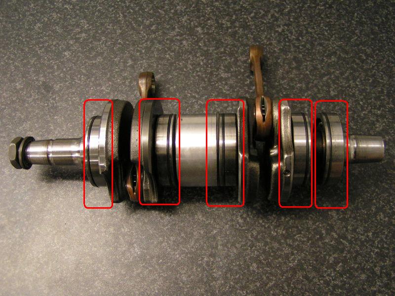
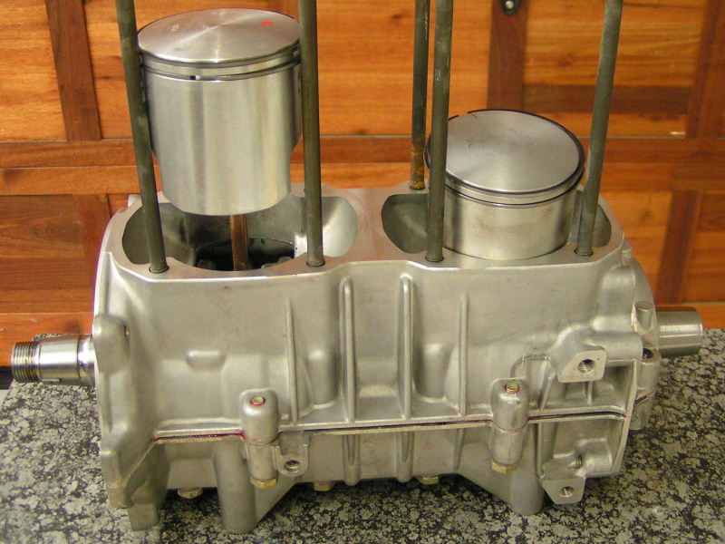
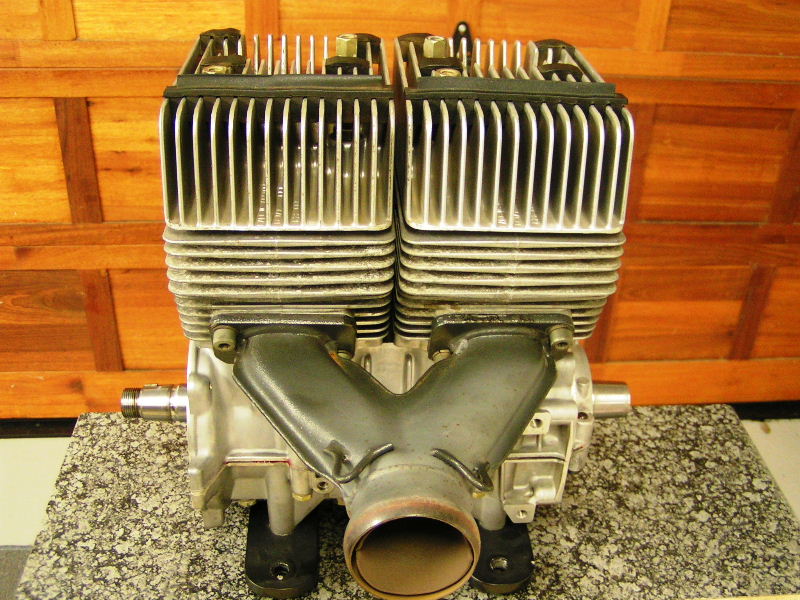
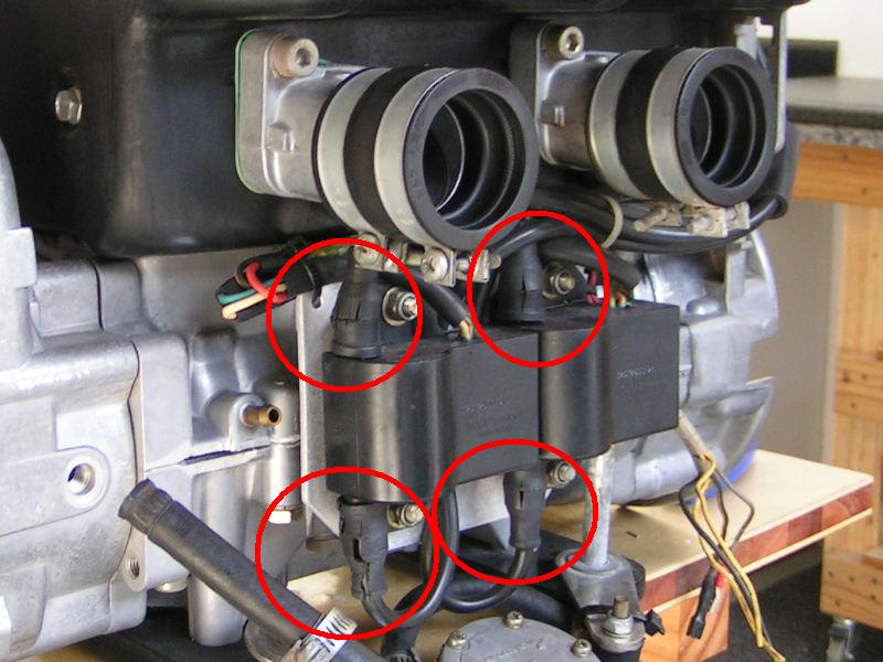
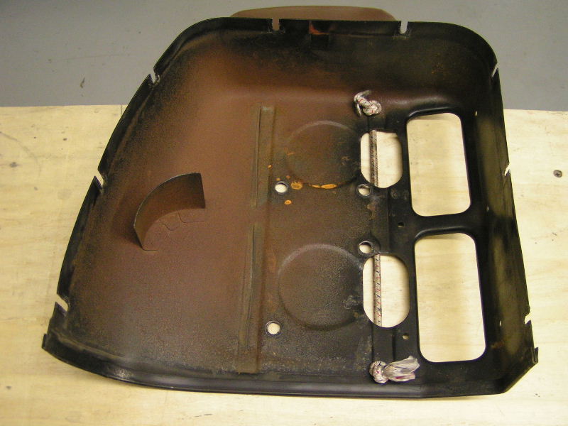
I borrowed the flying schools bearing and flywheel puller and started to strip the motor. The first thing I noticed after I pulled the cowls is the amount of corrosion that formed on the cowl and heads. Keeping in mind that my plane was always hangered except on the occasional fly-away. During those fly-aways I can only remember it standing in the rain under its cover once or twice. In addition I can only remember flying in the rain once or twice as well. The corrosion wasn’t visible on the outside on the motor, and it was kind of a shock to me because I typically keep my motor very clean. Now I can imagine what motors look like standing outside, or even at the coast!
Image
Image

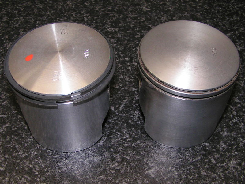
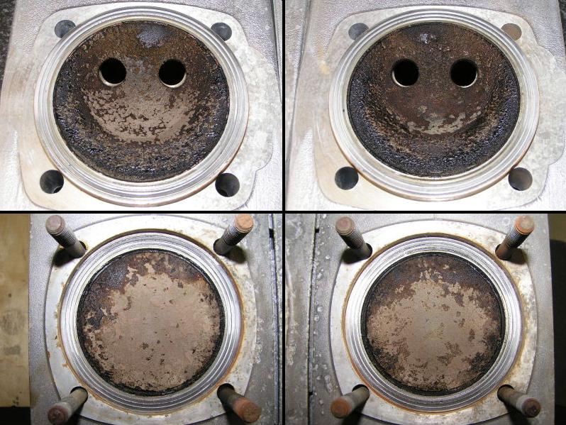
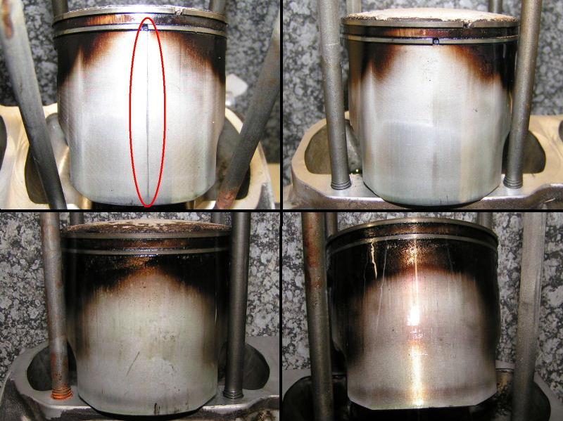
The next picture shows close-ups of the heads and piston tops. A fair amount of carbon formed burning a nice muddy brown. The camera flash makes it look lighter than it is. The experts tell me this is a sign of good burning motor, the jetting is just right.
Image

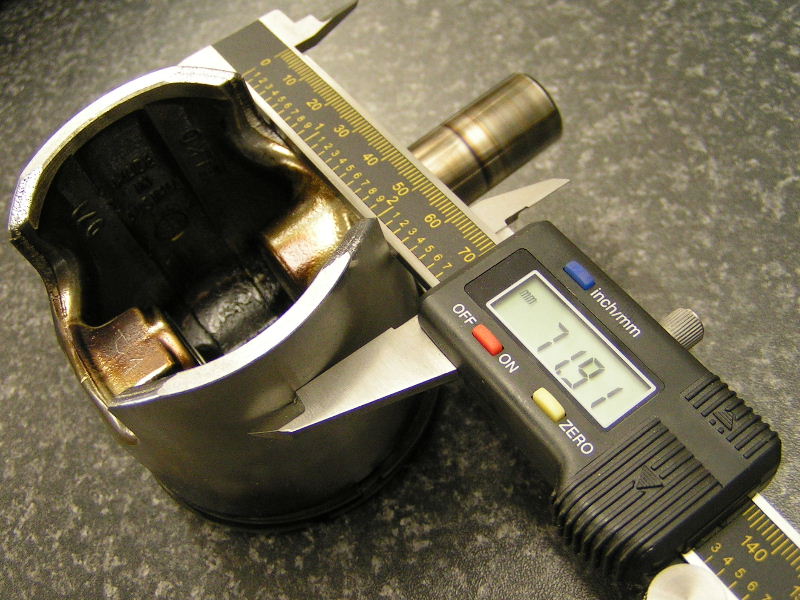
Next I inspected the rings. Both the top rings were nice and loose, but both bottom rings was stuck on 50% of the diameter of the piston side.

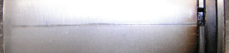
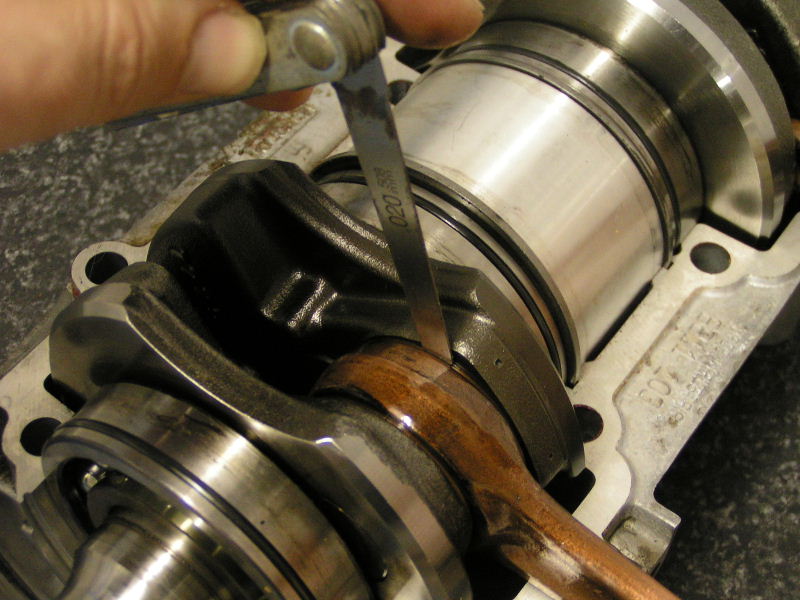
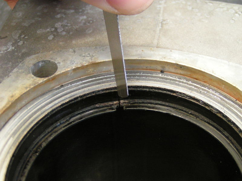
Then I noticed potential problem #1. The magneto side piston had a slight score line right down the centre in the middle of the intake manifold side. It is almost as if something very small went down the intake manifold and scored the side of the piston. It is just visible and one can hardly feel it, but it is there. I checked the cylinder walls and there is no scuffing. What ever small this was it did nut hurt the walls. Below is the intake manifold side view of pistons is on top with the corresponding exhaust side below.
Image

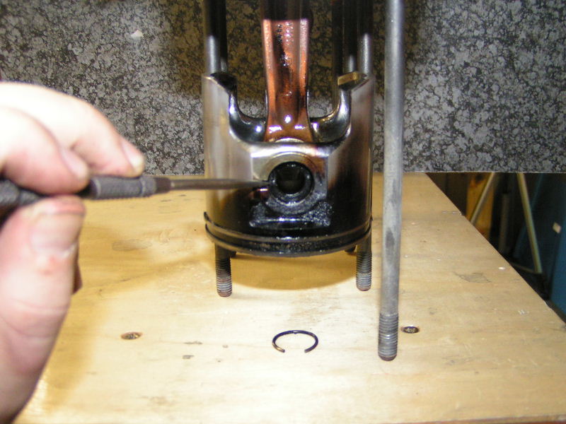
Next I turned the motor upside down and removed the circlips from the piston wrist pin. You can see where you insert a pick to remove the circlip shown on the table.
Image

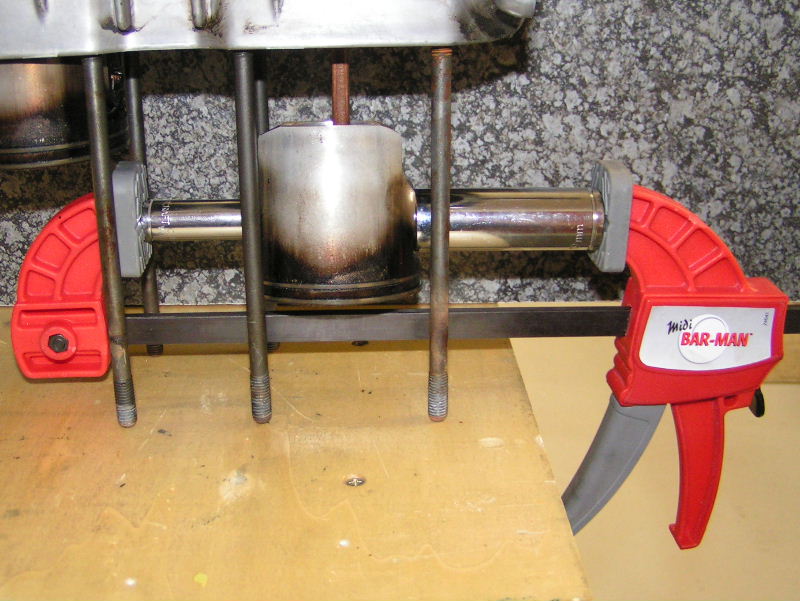
Next I pondered a while how to best remove the wrist pins, since I do not have a wrist pin puller…and then Eureka I got an idea that worked very well. I used 2 deep sockets and a big clamp. The small socket is smaller than the wrist pin and pushed it out into the bigger socket. I used 12mm and 19mm deep sockets and the wrist pin slid out without putting a lot of force on the clamp. Very easy, but pictures speak a thousand words. See below:
Image
Image

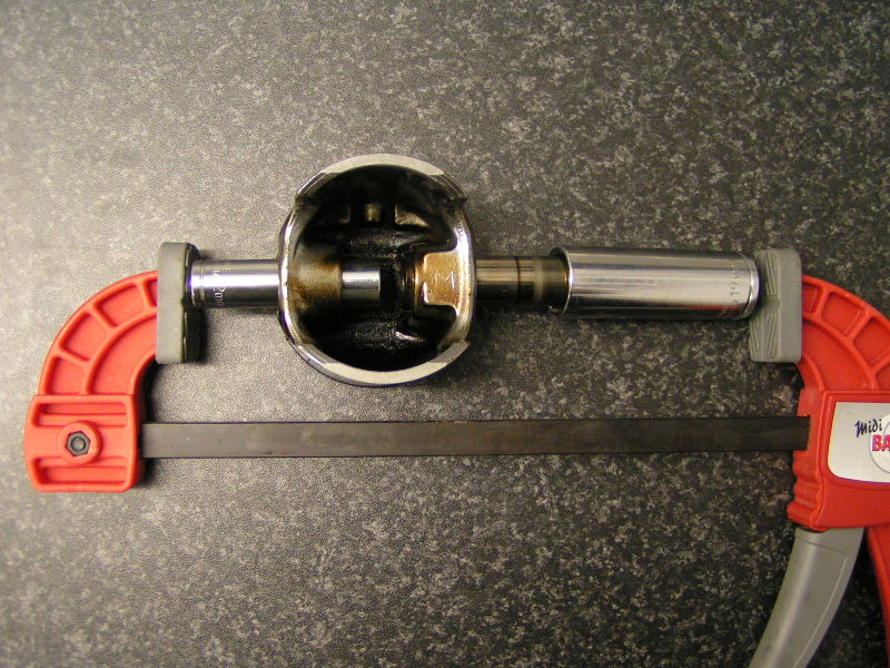
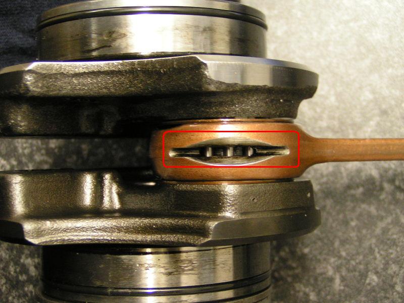
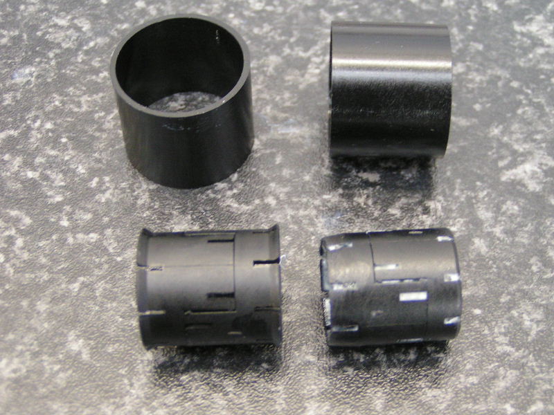
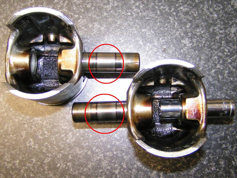
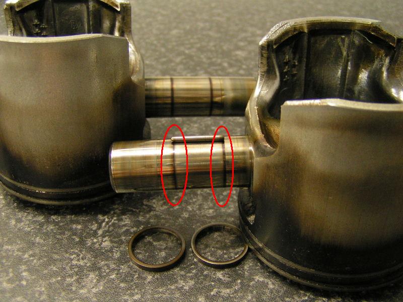
After removing all 31 needle pin bearings and the 2 rings I noticed problem #2 on the motor. Notice the 2 rings on the wrist pins. If you look at it closely you can see it is “blue-ing”, the ring is dark blue in colour which means the metal got hot and ‘burned’. It was evident on both wrist pins and occurred exactly where the needle pin bearings run as the pictures below depict. This means that some time during the motor’s life that the wrist pins did not get enough lubrication and hence the metal got hot and ‘burned’. Anybody got any ideas on why and when this happens???
Image
Image

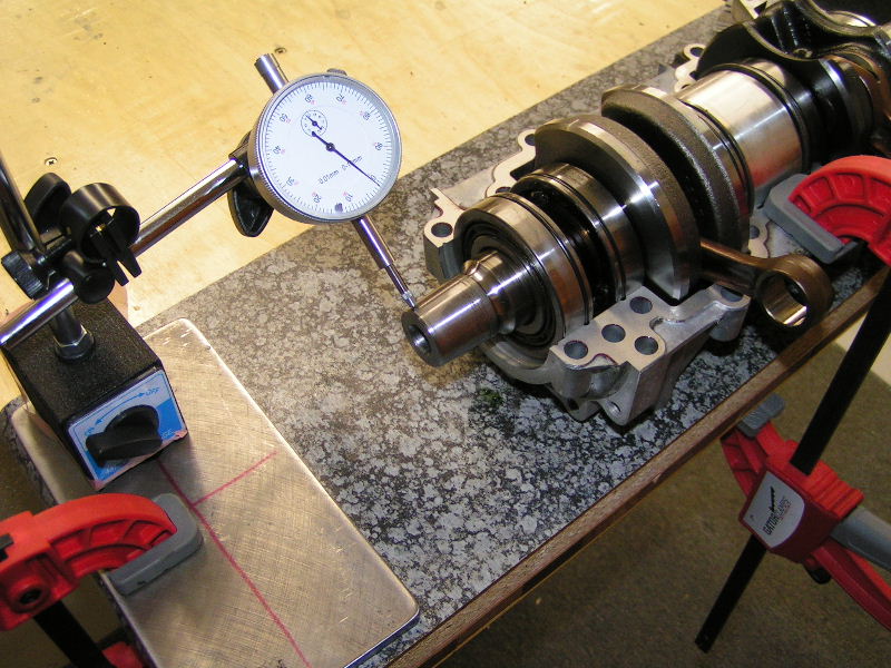
Well I still need to open up the crank case and inspect the crank and measure up the pistons, cylinders and crank, but will do that in the next week or so. If you guys are interested I will take pictures of the whole process and post it here...Let me know?

Any case I need to take my pistons and wrist pin to the experts to inspect and see what they say about the 2 potential problems I have found so far. In the mean time you guys can speculate in the forum below and tell me what you think the verdict will be. Your comments appreciated.

Kind Regards
Rudi
Last edited by RudiGreyling on Mon Jan 15, 2007 2:34 pm, edited 3 times in total.
"Science, freedom, beauty, adventure - Aviation offers it all"
http://www.RudiGreyling.com
User avatar
RudiGreyling
Top Gun
Top Gun
Posts: 695
Joined: Fri Jun 03, 2005 9:10 am
Location: The Coves
Contact:

Postby RudiGreyling » Mon May 29, 2006 8:18 am

PART 2:
=====

Hi Guys,

I started to measure up and inspect the parts in detail

After a bit of cleaning and showing the scratch on the piston to some experts it is clear that this scratch could actually be a crack and it is quite deep. That means this piston is kapoet, I will need to get a new one. The 2 expert guys I showed this to are still scratching their heads as to how this could have happened, since there is no evidence of any foreign objects. Hmmm good thing I decided to inspect my motor, who knows how long it would still have lasted…
Image

Any case I started to measure up the components to see how they compare to the Rotax wear limits. First the pistons, you measure 90 degrees to the wrist pin 18mm up from the bottom.
Image

Next I split the crank case, and with the crank still in the lower halve check the crank for out of round with a dial gauge. Check both the PTO (Power Take On) Gearbox side and Mag Side it should be less than 0.03mm
Image

Next I checked the axial play, with a feeler gauge between the conrod and the trust bearing, it should be less than 1mm.
Image

I took out the crank and inspected the 5 roller bearings. Firstly spinning them freely to see if I can detect any anomalies. Then I put some force on it with my hand and turning them through 360 degrees to see if I can detect any anomalies. Then you want to move them back and forth to see that they do not have excessive play on them, keeping in mind ball bearing do have some play.
Image

Next I inspected each and every ‘ball’ in the ball bearing that you can see, to check for pitting. So far everyting is clear.
Image

The last crank check is to rotate the conrod and inspect the rollers inside as best you can for pitting and or blue-ing.
Image

I started to measure everything up and made a table to compare to recommended wear limits. I will finish up the measurements and update the table in the next day or so.

Updated: I finished measuring everything
You have to measure the cylinders in 6 places to check out of round and conicity.
Image
Image

Measure the ring gap 5mm from the top.
Image

Here is the table with measurements
Image

The verdict: 1 new piston set, then new rings for the 2nd piston set, re-hone both cylinders, that will ensure the 2 pistons compression ratios are in sync. Though the experts say I can re-use the wrist pins with the blue burned marks on since they do not have any pitting on them I decided I will replace both wrist pins and all the needles, thrust washers and circlips.

Now I have to clean everything, purchase a couple of parts and start the re-assembly.

Groete,
Rudi

PS: Thanks to Fred (Airborne Sport) and Glen (Micro Flight Aviation) for their assistance.
Last edited by RudiGreyling on Mon Jan 15, 2007 2:48 pm, edited 5 times in total.
"Science, freedom, beauty, adventure - Aviation offers it all"
http://www.RudiGreyling.com
User avatar
RudiGreyling
Top Gun
Top Gun
Posts: 695
Joined: Fri Jun 03, 2005 9:10 am
Location: The Coves
Contact:

Postby RudiGreyling » Mon May 29, 2006 8:19 am

PART 3:
=====
Friday 2 June:
----------------
This moring I took the crank to a bearing inspection place in Jet-Park. They clean the crank and then spin up each rolller bearing and 'listen' / monitor each bearing for small deviations with sensative electronic equipment. They just phone me and told me all the bearings is fine, they should be able to last for the same amount of time (435Hours) at the same load and conditions.

They charged +/-R700, in my opinion it is good 'insurance' for a critical part of our little motors i.e. the crank which is also a very expensive component i.e. R5000+. Call it 14% 'insurance' levy vs new part to make sure it will last for another 435Hours.

If you guys are interested when I get the print outs and test results I'll see If I can load them up here. Let me know

Monday 5 June:
------------------
The crank back from its health inspection, nicely sealed.
Image

The heads clean up nicely with the aid of a soft brass brush, just be carefull not the scratch the outer rings where the head seals! Do not use a metal or stainless wire brush it will scratch the Heads!
Image

Spot the new piston :lol: The old one cleans up nicely with a lot of elbow grease and green scotch bright, just ensure you clean in the same direction as the oil groves on the side of the piston. I weighed both pistons and they are within 2 grams of each other, my scale is only accurate within 2 grams so they are OK!
Image

The needle bearing come in a housing like this, I grinded of the shoulders on the inner ring on the right hand one. This then allows one to push it out the piston side during the installation of needle bearings and wrist pin.
Image

The 2 crank halves joined with gasket maker, and pistons back on
Image

Put the cylinders on with gaskets and finger tight the heads, then use your exhaust manifold to allign the cylinders before torqueing the heads down.
Image

The rest of the assembly is pretty straight forward. I decided to overhaul my fuel pump and carbs while I'm at it as well.

I hope you guys enjoyed it and find it worthwile.

Kind Regards
Rudi
Last edited by RudiGreyling on Mon Jan 15, 2007 2:40 pm, edited 4 times in total.
"Science, freedom, beauty, adventure - Aviation offers it all"
http://www.RudiGreyling.com
User avatar
Morph
The Big Four K
The Big Four K
Posts: 5176
Joined: Wed May 25, 2005 3:34 pm
Location: Cape Town

Postby Morph » Mon May 29, 2006 10:24 am

The black marks down the sides of the pistons is caused by blow by, i.e. the hot gasses leaking past the rings . This can be very easily seen from the exhaust port if you remove the manifold. This is a sure sign of stuck rings and necessitates decoking the motor.

When I stripped my 540 hour motor I had the same burn marks etc on the pistons and the crowns and heads were quite heavily coked. The wristpins did not have the blue burn marks on them so I believe your suspicions are correct wrt the engine over heating at some stage.

Be vary carefull when you remove the rings so as not to over stretch them. Once removed put them back into the barrel, use the piston to push them all the way to the top and then measure the gap. If it is under 1mm your rings should be fine.
Greg Perkins
User avatar
RudiGreyling
Top Gun
Top Gun
Posts: 695
Joined: Fri Jun 03, 2005 9:10 am
Location: The Coves
Contact:

Postby RudiGreyling » Mon May 29, 2006 10:43 am

Hi Morph,

thanks, the mark I was referring to is marked with RED eclipse in one of the pictures, top Left side view of the piston. It is not the typical Carbon marks. It is definitely some scuffing, very faint, but it is there.

Ja I know, I still need to measure everything, including ring gap, it needs to be less than 1mm. When I get a chance this week I’ll measure everything up and report back in PART 2.

Kind Regards
Rudi
"Science, freedom, beauty, adventure - Aviation offers it all"
http://www.RudiGreyling.com
User avatar
Morph
The Big Four K
The Big Four K
Posts: 5176
Joined: Wed May 25, 2005 3:34 pm
Location: Cape Town

Postby Morph » Mon May 29, 2006 11:01 am

Yeah I saw that. Whatever went down the side had to have come past the top ring first and how is not obvious. Is it not possible that a piece of carbon came loose from area in the gap on the second ring or whoever decoked the motor previously left a bit of dirt at that joint. Alternatively dirt came in via the intake manifold. I suppose it could have been anything, sand particle ?

The point I was making about the blow by was for others benefit, since the pics clearly show it. If you get blow by then your rings are stuck or worn.
Greg Perkins
Bumpy
First solo
Posts: 87
Joined: Wed Dec 28, 2005 9:32 am
Location: Maputo

Postby Bumpy » Mon May 29, 2006 2:13 pm

Hi Rudi

Thanks for the detailed info and pics!
I look forward to your next post
How do mosquitoes get this high?
nickjaxe
Look I'm flying
Look I'm flying
Posts: 221
Joined: Wed Oct 05, 2005 9:42 pm
Location: North Cheshire in the UK.

Postby nickjaxe » Tue May 30, 2006 12:08 am

Hi rudi fantastic pictures hoping to do my 503 soon please post more, very interesting, also pictures of any special tools you use if possible.

Nick in the UK.
User avatar
RudiGreyling
Top Gun
Top Gun
Posts: 695
Joined: Fri Jun 03, 2005 9:10 am
Location: The Coves
Contact:

Postby RudiGreyling » Tue May 30, 2006 8:38 am

nickjaxe wrote:Hi rudi fantastic pictures hoping to do my 503 soon please post more, very interesting, also pictures of any special tools you use if possible.

Nick in the UK.
Thanks, I will update with as much info as possible.

On the tools: So far the only special tools required was the flywheel puller and gearbox gear puller. When the engine was ready with the pull rope cover removed and the gearbox rear cover removed I took it to my friendly rotax engine repair shop. They have the tools and it will take them 2 minutes to remove these for you if the covers are removed.

If you re-assemble the pistons you will need a small tool to place and space the needle bearings. I don't have one, so I will need to borrow one somewhere or make another plan when I get there, but I will post pictures. Anyone got any good alternative 'BOERE' ideas how to space the needle bearings on re-assembly please post below.

Kind Regards
Rudi
"Science, freedom, beauty, adventure - Aviation offers it all"
http://www.RudiGreyling.com
User avatar
Smiley
Pilot in Command
Pilot in Command
Posts: 922
Joined: Tue Jun 14, 2005 1:39 pm
Location: 100% Sky

Postby Smiley » Tue May 30, 2006 1:04 pm

Hello Rudi

Just posting this, so I can receive the updates!!

You can get that small tool you need for the needle brearings from Fred. I used his the last time...... :roll:
Flying tha beast named "Wollie"
ZS-WGT

Springs 122.40
User avatar
Morph
The Big Four K
The Big Four K
Posts: 5176
Joined: Wed May 25, 2005 3:34 pm
Location: Cape Town

Postby Morph » Tue May 30, 2006 2:08 pm

greylingr wrote:Anyone got any good alternative 'BOERE' ideas how to space the needle bearings on re-assembly please post below.
Rudi,

we used lekker dik grease, coated the wristpin, stuck the needle bearings on to them, then inserted the whole lot into the conrod. Slowly pull the wristpin out and the needle bearings will stay in place. Place the piston over the conrod and carefully line up the wristpin. Push it carefully through. Remmember there must be 31 needle bearings.

If you make an insert the same diameter as the wristpin you will have to remove the circlips on both side of the piston so you can push the insert out the one side when you insert the wristpin from the other side
Greg Perkins
nickjaxe
Look I'm flying
Look I'm flying
Posts: 221
Joined: Wed Oct 05, 2005 9:42 pm
Location: North Cheshire in the UK.

Postby nickjaxe » Tue May 30, 2006 8:03 pm

Hi again rudi hope you don't think I am cheeky but next time you have the camera out I wonder if you could take a picture of the head for me, I know you have already posted some but what I need to be able to see is the depth and shape of the groves on the sealing surface on the head cannot quite see it in your pics, so a good close up would be fantastic, I have a persistent oil leak from my head changed the sealing rings re-tightened the heads ect, it has been suggested it may be because a past owner of my aircraft may have had the heads skimmed and in doing took to much of the sealing grove away so it would be nice to see how they should look for when I strip it all down.

Nick.
User avatar
RudiGreyling
Top Gun
Top Gun
Posts: 695
Joined: Fri Jun 03, 2005 9:10 am
Location: The Coves
Contact:

Postby RudiGreyling » Wed May 31, 2006 2:32 pm

nickjaxe wrote:<SNIP>...if you could take a picture of the head for me, <SNIP> I need to be able to see is the depth and shape of the groves on the sealing surface on the head cannot quite see it in your pics, so a good close up would be fantastic <SNIP>.
Nick, I'll see what I can do for you in the next day or so. Rudi
"Science, freedom, beauty, adventure - Aviation offers it all"
http://www.RudiGreyling.com
User avatar
RudiGreyling
Top Gun
Top Gun
Posts: 695
Joined: Fri Jun 03, 2005 9:10 am
Location: The Coves
Contact:

Repair Manual Softcopy

Postby RudiGreyling » Wed May 31, 2006 2:39 pm

Hi Guys,

Does anyone have the 503 Repair Manual in Softcopy (.PDF) available???

I have a hardcopy, but I would like to post the links to it since you really need to read it to work on these engines. It is a good reference, to keep it together with the photos above.

I have the installation, operators and maintenance manauls in softcopy, but not the repair manual. I'd like to post all together.

Dankie, Groete,
Rudi
"Science, freedom, beauty, adventure - Aviation offers it all"
http://www.RudiGreyling.com
nickjaxe
Look I'm flying
Look I'm flying
Posts: 221
Joined: Wed Oct 05, 2005 9:42 pm
Location: North Cheshire in the UK.

Postby nickjaxe » Wed May 31, 2006 8:09 pm

Thanks rudi would be great if you can, just had a look at my rotax pdf files but I have the same as you operators/maintainance only.

Nick.

Who is online

Users browsing this forum: No registered users and 73 guests