Page 1 of 1
Rotax rev counter: wiring diagram
Posted: Thu Feb 17, 2011 8:14 pm
by Wannabe pilot
I have recently obtained a Rotax rev counter, but have no idea how this is wired up. I would like to install it on my Windlass. There are only two connections on the back - marked positive and negative. Do anyone know how the wiring should be connected, or maybe have a wiring diagram that can be posted?
Any help would be appreciated.
Re: Rotax rev counter: wiring diagram
Posted: Thu Feb 17, 2011 9:40 pm
by Duck Rogers
Sure.........negative to ground and positive to the GREY wire coming out from the stator coil. Assuming you have a Rotax 2 stroke engine in that Windlass

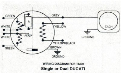
- Image1.jpg (22.21 KiB) Viewed 2112 times
Re: Rotax rev counter: wiring diagram
Posted: Fri Feb 18, 2011 7:33 pm
by Wannabe pilot
Thanks - yes, Rotax DCDI
Re: Rotax rev counter: wiring diagram
Posted: Sat Feb 26, 2011 6:24 pm
by Wannabe pilot
Problem!!! ------- I wired the rev counter up according to the diagram, but now the revs it show seems to be at least double what they should be. It revs up easily to 8000, which of course cannot be. I noticed that when I do mag checks, the revs show no reaction when the one switch is switched of, but decrease about 1000 rpm when the second switch is switched off. This must be something to do with the double ignition, I think, but how do I rectify it? I picked the only grey wire I could see - to me it seems to be coming from the magneto and not the stator. As far as I could see, there are no grey wires coming from the stator, unless I missed it in the harnass?
Re: Rotax rev counter: wiring diagram
Posted: Sat Feb 26, 2011 7:03 pm
by German
Check your earth
Re: Rotax rev counter: wiring diagram
Posted: Sat Feb 26, 2011 11:17 pm
by Duck Rogers
You sure you have a tacho for a dual ignition?
There are different ones for dual and single ignition
Yip, that's the right grey wire. There is only one